
Key takeaways
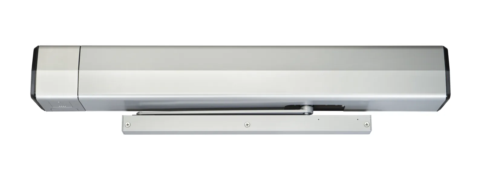
- Norton's catalog comparison lists eight low-energy operator series, electromechanical and electrohydraulic. This page covers only the 6000 Series, a frame-mounted electrohydraulic operator that incorporates a door closer.
- The single-door models differ in the side of the door they mount on, how far the door opens and the frame reveal they fit.
- The catalog gives the power input as 120 VAC, 60 Hz (+10%, -15%), with a current draw of 0.9A for a single unit and 1.8A for a double unit.
- Hold-open time, speed, force and the closer valves are settings Norton's instructions name for the installer.
- On labeled fire or smoke barrier doors, Norton's installation sheets require the operator's power to come through normally closed contacts of the alarm system.
Models
Which 6000 Series model do I have?
Norton's product page calls the 6000 Series a WiFi-enabled operator and "a heavy-duty unit designed for rigorous, high-use applications." Its six single-door models mount on the hinge (pull) side, the side the door swings toward, or the stop (push) side. The frame reveal is how far the face of the door is set back from the face of the frame.
In Norton's catalog, the 5700 and 5500 are the other frame-mounted electrohydraulic series; its other five series are electromechanical.
The documents differ on handing: the catalog lists the series as "Non-handed", while the pull side instructions label the 6051 "(Handed)" and the push side instructions label the 6031 "(Handed)".
Norton's documents now carry the Norton Rixson name, a brand associated with an ASSA ABLOY Group company. For how low-energy operators work in general, see the guide to low-energy door operators.
| Model | Side of door | Arm | Door opening | Frame reveal | Drop version in the catalog (needed if ceiling clearance is less than 5" (127); order with suffix D) | Auxiliary stop (catalog) | Auxiliary stop (installation sheet) |
|---|---|---|---|---|---|---|---|
| 6011 | Hinge (pull) | Rigid arm and slide track | 85° to 110° (5° increments) | 1/8" (3) | Not listed | Recommended | "Auxiliary door stop (by others) required." |
| 6051 | Hinge (pull) | Double egress and slide track | 85° to 110° (5° increments) | 1/8" to 3" (3 - 76) | Not listed | Recommended | "Auxiliary door stop (by others) required." |
| 6021 | Stop (push) | Standard-duty double lever arm | Up to 110° | 2-3/4" to 6-7/8" (70 - 175) | Available | Required | "Auxiliary door stop (by others) required." |
| 6031 | Stop (push) | Standard-duty double lever arm | From 110° to 180° | 2-3/4" to 6-7/8" (70 - 175) | Available | Required | "Auxiliary door stop (by others) required." |
| 6061 | Stop (push) | Heavy-duty double lever arm; Unitrol Series in its installation instructions, and the catalog shows a heavy-duty Unitrol arm | 85° to 110° (5° increments) | 2-1/4" to 4-3/4" (57 - 121). Catalog footnote: reveals less than 2-1/4" (57) may be achieved by field cutting the adjusting rod | Available | Not named in the catalog note | "Auxiliary door stop (by others) required." |
| 6071 | Stop (push) | Heavy-duty double lever arm; Unitrol Series in its installation instructions | 85° to 110° (5° increments) | 4-13/16" to 7-3/8" (122 to 187) | Available | Not named in the catalog note | "Auxiliary door stop (by others) required." |
Source Norton's 6000 Series product page, the technical information tables and notes in its Operators Catalog, its Low Energy Operators brochure and the three single-door installation instructions.
Pairs
Units for pairs and double egress doors
For a pair of doors, the catalog shows double units with a D prefix. For double egress doors, whose two leaves swing in opposite directions, it lists right-hand and left-hand units in three reveal ranges. Double-door programming has its own manual.
| Model | Door | Side or frame reveal | Drop version in the catalog | Auxiliary stop (catalog) |
|---|---|---|---|---|
| D6011 | Pair of doors | Pull side | Not listed | Recommended |
| D6051 | Pair of doors | Pull side | Not listed | Recommended |
| D6021 | Pair of doors | Push side | Available | Required |
| D6031 | Pair of doors | Push side | Available | Required |
| D6061 | Pair of doors | Push side | Available | Not named in the catalog note |
| D6071 | Pair of doors | Push side | Available | Not named in the catalog note |
| D6001DER | Right-hand double egress doors | See the three reveal ranges below | Not listed | Not named in the catalog note (it names "D6001DE pull side") |
| D6001DEL | Left-hand double egress doors | See the three reveal ranges below | Not listed | Not named in the catalog note (it names "D6001DE pull side") |
| D6001DE | Double egress | Reveal 2-1/4" to 3" | Not listed | Recommended for "D6001DE pull side" |
| D6001DE1 | Double egress | Reveal 3-1/16" to 4-3/4" | Not listed | Not named in the catalog note (it names "D6001DE pull side") |
| D6001DE2 | Double egress | Reveal 4-13/16" to 7" | Not listed | Not named in the catalog note (it names "D6001DE pull side") |
Source Norton's 6000 Series product page, and the door opening examples, double egress table and notes in its Operators Catalog.
Power
How is it powered, and what door can it run?
Where Norton's documents give different door widths, the table gives both.
| Item | What Norton lists | Document |
|---|---|---|
| Power input | 120 VAC, 60 Hz (+10%, -15%) | Catalog |
| Current draw | 0.9A (single), 1.8A (double) | Catalog |
| Circuit breaker | 3 amps | Installation instructions |
| Auxiliary output | 24 VDC @ 1.3A | Catalog |
| Relay output | SPDT, for controlling electric strikes or electric locks; not to exceed 1 amp @ 30 VDC | Catalog |
| Maximum wire size | 12 AWG at power input connection; 14 AWG at all other terminals | Installation instructions |
| Wire | Copper wire only at the power input connection and power output contacts | Installation instructions |
| Permanent wiring | "To be implemented as required by local codes" | Installation instructions |
| Maximum door weight | 250 lbs | Catalog |
| Door weight | 100-250 lb. (43-113 kg) | Installation instructions |
| Door width | 36" to 48" in the feature list; minimum 36" (91cm) in the technical information table | Catalog |
| Door width | 28" - 48" (71-122 cm) | 6061/6071 installation instructions |
| Rate of operation | Not to exceed 300 cycles of opening and closing per hour | Installation instructions |
Source The electrical data and feature list in Norton's Operators Catalog and the technical data in the three single-door installation instructions.
Standards
What standards and listings does Norton state?
The table gives each standard or listing Norton states. The documents differ on outdoor use: the installation sheets' safety warning reads "FOR INDOOR USE ONLY", while the catalog's comparison table marks the series for exterior doors.
On presence sensors over the door, the installation instructions say: "If desired, overhead presence devices can be provided for an extra level of protection. Consult local authority having jurisdiction. These are not required by current ANSI/BHMA A156.19 standards."
The catalog lists a 679 signage kit as "supplied standard": push and pull signs, 1 per switch, and a door decal reading AUTOMATIC CAUTION DOOR, 2 per operator. The installation sheets add that the door must be visible by the person operating the activation switch.
| Standard or listing | What Norton says | Document |
|---|---|---|
| ANSI A156.19 | "These products are designed to conform to this specification 'for power assist and low energy power operated doors.'" | Installation instructions |
| ANSI A156.19 | Designed to exceed all the requirements for "Low Energy Power Operated Door" | Installation instructions |
| ANSI/BHMA A156.19 | "ANSI/BHMA A156.19 certified" | Catalog |
| UL 325 and UL 10C | "ETL Certified: Operator conforms to ANSI/UL standard 325 for automatic closing doors and UL10C Positive Pressure Fire Test for Door Assemblies." | Installation instructions |
| UL 10C | "UL10C positive pressure push (3-hour), pull (90 min)" | Catalog |
| Fire and smoke barrier doors | ETL tested to UL-cUL standards for automatic doors used on fire and smoke barrier doors | Catalog |
| California State Fire Marshal | Listing 3266-0944:0110 | Catalog |
| Americans with Disabilities Act | "These door operators can be installed and adjusted to conform with A.D.A. regulations." | Installation instructions |
| ANSI A117.1 | "These door controls permit door assemblies to conform to the requirements of this specification" | Installation instructions |
| Door type and location | Use only with pedestrian swing doors; "FOR INDOOR USE ONLY" | Product safety warning, three single-door installation sheets |
| Exterior doors | Marked for "Use on exterior doors" | Catalog comparison table |
Source The standards, safety warning and notes in Norton's three single-door installation instructions, and the certification list, comparison table and accessories pages of its Operators Catalog.
Inputs and outputs
What opens it, and what can it switch?
Norton's installation instructions list push plates, access control, mats, touchless wall switches and similar devices as activation devices. In the programming manual's diagrams, activation can be a wall switch, card reader or key switch with normally open momentary dry contacts: a switch that closes briefly and carries no voltage of its own.
The three configurations Norton describes are activation by push plates or wave-to-open switches; Push & Go, where a door pushed or pulled slowly 15° by hand then opens automatically to full open; and use as a manual door.
The manual describes two relay outputs, labeled RLY 1 and RLY 2, each with a selectable function: 3 Second Relay, Open POS Relay, Closed POS Relay or Door Latch Relay.
In its lock diagrams, a 24VDC fail secure electric strike or electric exit device keeps the door locked during a power failure; a 24VDC fail safe electric strike or electromagnetic lock leaves it unlocked. Both use the relay (Relay 2), Latch Retraction and/or Open Delay, each of which must be turned on in setup.
| Input function | What the manual says it does |
|---|---|
| Activation 1 | Momentary contact closure cycles the door through an automatic open / close cycle. Tied to Open Delay 1. |
| Activation 2 | Momentary contact closure cycles the door through an automatic open / close cycle. Tied to Open Delay 2. |
| Executive Mode | A signal opens the door and keeps it open until a second signal is received or the door is moved by hand toward closed. |
| Emergency Interface Relay | Continuous contact closure puts the operator in a passive closer mode, where the door functions as a door closer and accepts no activations. |
| Blow Open | With the 3-position switch On, an alarm system signal opens the door, and it stays open until that signal is stopped. |
| Blow Open Override | With the 3-position switch in the On or Off position, the door opens at set position until power is turned off. |
| Obstruction 1 | Contact closure while the door is closing triggers the operator to return to the open position. |
| Obstruction 2 | Contact closure while the door is opening stalls the operator. If not removed after 10 seconds, the operator returns to closed. |
| Outside Push Button Disable | When this contact is closed, the outside push button is disabled. |
Source Norton's single-door installation instructions and the input, relay and wiring diagram pages of its 6000 Series Programming & Wiring Instructions.
Settings
The settings Norton's instructions name for the installer
These settings are for the installer, and Norton's safety warnings say: "Failure to adjust operator properly may cause severe injury or death." If the door seems too fast, too forceful or open too long, the next step is a service call, not a changed setting.
The closer has four valves: S for the sweep range from full open to 10°, L for the latch range from 10° to closed, B for the strength of cushioning in the backcheck range (the slowing near full open), and P for the angle where backcheck is felt while opening.
Force, the effort to open or close the door by hand, comes from the closer spring. The installation instructions note: "A closer set to ADA required 5 lbs opening force may not be strong enough to close door due to latching hardware, air pressure, or frame issues."
They give the hold-open time, during which the motor holds the door open, as 0 to 30 seconds, with "A.D.A. 5 seconds min." beside it, and an obstruction time of 0 to 5 seconds.
The programming manual covers setup from the onboard LCD screen and joystick or a WiFi smart device. Its options include the arm type (push or pull), the operator model, the open and closed positions and a Learn function.
Open Stall Force is the force when the door is slowed to a stop while opening, from 1 (lightest) to 10 (strongest); Obst Det Sens is how long the door pushes against an obstruction before stalling or reversing. The manual adds: "Measure the door force to ensure compliance with applicable standards and codes."
The manual ties its Speed/Force and Timing/Location settings to the standard's requirements for door weight and width, printing the standard as "ANSI BHMA A159.19" where Norton's other documents print A156.19. Table I is based on a kinetic energy of 1.25 lbf-ft.
| Door leaf width | 100 lb | 125 lb | 150 lb | 175 lb | 200 lb |
|---|---|---|---|---|---|
| 36" (914) | 3.0 sec | 3.5 sec | 3.5 sec | 4.0 sec | 4.0 sec |
| 42" (1067) | 3.5 sec | 4.0 sec | 4.0 sec | 4.5 sec | 4.5 sec |
| 48" (1219) | 4.0 sec | 4.5 sec | 4.5 sec | 5.0 sec | 5.5 sec |
Source The safety warnings, adjustments and technical data in Norton's single-door installation instructions, and the setup options and Table I in its Single Door Installation Programming & Wiring Instructions.
Behaviour
What it does with power off, an obstruction or a fault
With or without power, the installation instructions say the door works like a standard door closer when pushed or pulled open by hand, and the closer's spring force keeps it closed.
Norton's catalog lists obstruction detection both ways: the door closes if it hits an obstruction while opening, and reopens once if it hits one while closing. If obstructed during that second closing cycle, the installation instructions add, it stops and rests against the obstruction using only the closer spring's force.
An overload safety shut-off closes the door after 3 minutes of receiving an activation signal, when the inverter times out, to prevent motor and inverter damage.
The three-position selector mode switch has Off, which disables signal inputs unless Blow Open is activated; On, which activates them; and Hold Open. With Infinite Hold Open, the door holds at the set position until power is turned off.
A steady red POWER LED on the control board means power is applied; the number of flashes identifies an error, as the table shows.
| Flashes or message | Error | Description |
|---|---|---|
| 1 flash | Configured Settings Error | Configured settings have been lost. |
| 2 flashes | 24VDC Power Error | Operator 24V power supply is malfunctioning or there is a wiring problem. |
| 3 flashes | Learn Error | Learn process failed, perhaps due to an obstruction, faulty hinges, or other mechanical issue. |
| 4 flashes | Motor Error | There is a problem with main motor. |
| 5 flashes | Over Temperature Error | Motor has overheated. |
| 6 flashes | Power Board Error | Power board is not plugged in. |
| 7 flashes | Temperature Probe Error | Motor temperature probe is disconnected or damaged. |
| 8 flashes | Sensors Error | Position sensors governing operator are not working correctly. |
| 9 flashes | Motor Duration Error | Motor ran longer than allowed. |
| 10 flashes | Double Door Error | Cable connecting the two doors is disconnected or damaged. |
| Screen message | Drive Disabled | The selector mode switch is in the Off position. |
| Screen message | Over Voltage | Line voltage has exceeded 145VAC. |
| Screen message | Under Voltage | Line voltage has dropped below 80VAC. |
| Screen message | Presence Detect | A presence detector is attached and has been activated. |
Source The features list in Norton's Operators Catalog, the operation notes in its single-door installation instructions, and the error code table and troubleshooting guide in its Programming & Wiring Instructions.
Fire doors
Fire-rated doors and the fire alarm connection
Norton's three single-door installation sheets say: "Labeled fire or smoke barrier door assemblies require 120VAC 60Hz power input be supplied through normally closed alarm contacts of the alarm system / alarm panel."
The programming manual's diagram for an electric latch retraction exit device with Blow Open notes: "This application must be approved by local authority having jurisdiction (AHJ)." It also says the operator's main power input must be wired into the building's back-up power supply, and adds: "The exit device allows egress at all times, including during power failures."
The catalog lists Blow open for smoke ventilation, holding the door open for air or smoke until the alarm signal stops. The documents differ on a fire panel input: the programming manual defines an Emergency Interface Relay input, while the catalog's comparison table does not mark "Emergency interface relay (fire panel input)" for the 6000 Series.
Source Norton's three single-door installation instructions, the features list and comparison table in its Operators Catalog, and the Blow Open wiring diagram and input list in its Programming & Wiring Instructions.
Service
Installation and service on Norton operators
Norton's safety warnings say to install the operator only on a properly operating and balanced door, to have qualified service personnel make repairs to any hardware before installing the operator, and to test the door's features at least once a month.
Elwin Security installs, repairs and replaces door closers and low-energy door operators, including the Norton 6000 Series, as part of its commercial door closer and exit device service for commercial and multifamily properties in the San Francisco Bay Area. Calls are answered 8:00 AM-8:00 PM daily at (408) 539-0535.
Questions about the Norton 6000 Series
Questions and answers
Which Norton 6000 Series model goes on the pull side?
Norton lists two models for the hinge (pull) side of the door. The 6011 uses a rigid arm and slide track, and the 6051 is listed with double egress and slide track. The four push-side models are in the model table.
Can a Norton 6000 Series operator go on a fire-rated door?
Norton's catalog lists UL 10C positive pressure for push (3-hour) and pull (90 min) and ETL testing to UL-cUL standards for fire and smoke barrier doors. On labeled fire or smoke barrier doors, its installation sheets require the power input to come through normally closed alarm contacts.
What does a flashing red light on a Norton 6000 operator mean?
A steady red POWER LED means power is applied. Flashes identify an error, from 1 for lost configured settings to 10 for a disconnected or damaged cable between two doors; the error table lists all ten.
Sources and further reading
These sources back up the general guidance. Your building and the people who approve the work decide the details for your doors.
- Norton Rixson (ASSA ABLOY): 6000 Series low energy door operator product page
- Norton Rixson (ASSA ABLOY): Norton Rixson Operators Catalog (43492, 09/26)
- Norton Rixson (ASSA ABLOY): Norton Rixson Low Energy Operators Brochure (43550, 09/26)
- Norton Rixson (ASSA ABLOY): 6011/6051 Series (Pull Side) Power Operator Installation Instructions (80-9360-1040-020 Rev 4, 12/25)
- Norton Rixson (ASSA ABLOY): 6021/6031 Series (Push Side) Power Operator Installation Instructions (80-9360-1041-020 Rev 3, 12/25)
- Norton Rixson (ASSA ABLOY): 6061/6071 Unitrol Series Push Side Power Operator Installation Instructions (80-9360-1042-020 Rev 3, 12/25)
- Norton Rixson (ASSA ABLOY): 6000 Series Single Door Installation Programming & Wiring Instructions (80-9360-1043-020 Rev 6, 07/26)